The wind turbine commented |
(If your browser is set to block pop-ups you will need to disable this temporarily)
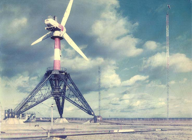
- "North" pillars: approximately 150 tonnes of concrete. Buried approximately 1m20. They supported the axes of rotation of the wind turbine to allow it to be tilted onto the research station.
- "South" pillar: approximately 100 tonnes of concrete. It allowed the anchoring and locking of the third leg when the wind turbine was vertical. Its offset allowed for tilting.
- From the left north pillar, the platform at the top of the tripod was accessed by a staircase which can be seen in the photo. The staircase led up to a first platform at the base of the central part of the tripod. The platform at the top of the tripod was reached by a vertical ladder along with the pivot. The upper platform of the tripod was 16 metres above the ground.
- Behind the left north pillar are the IPNs to support the weight of the machine when it was in a horizontal position.
- Behind this pillar is the laboratory of the research station.
- Above the tripod is the pivot of the wind turbine (painted in red and white). The pivot was in the form of a cone (in black on the photo) and was inserted into the axis of the tripod up to the base of its central part. It was steered by a set of ball bearings (at the bottom of the tripod) and a set of vertical rollers (at the top of the central part of the tripod).
- The top of the turbine was reached by a series of vertical ladders running along with the pivot between two airfoils and then around the upper nacelle located 32 metres above the ground.
- The nacelle housed the generator, disc brake, clutch and various equipment.
- Each blade of the propeller measured 15 metres, giving a diameter of 30 metres. For comparison, the wingspan of a Douglas DC3 (Dakota) is 28.90 metres. The swept area is therefore about 707 m2.
- From the south pillar, one can see the mining cable, laid on railway sleepers, connecting this foot to the south winch.
- In the foreground is the fourth blade. It had been used to perform stress tests in the laboratory. You can see the red "buns" which are the marks left by the stress cylinders during the tests. On the enlarged photograph, one can see holes a few centimetres in diameter every 20 centimetres on the leading edge of the blade. These are the locations of the spoilers which, by modifying the profile of the leading edge and the aerodynamics of the blade, served as an emergency brake in case of a runaway. I was about ten years old at the time and, with my brother, we spent hours playing acrobatic "aviators" on this life-size "wing".
- In the background on the right, the 60-metre pylon equipped with a windsock.
In this photo, the turbine is oriented in its actual direction of operation concerning the wind (see the windsock on the 60-metre tower on the right of the photo). The wind turbine was in "wind vane" mode: it was facing the wind, with the nacelle upright and the propeller to the rear.
In front of the nacelle, a mast can be seen which supported an anemometer allowing the exact measurement of the wind at the wind turbine. The air intake seen at the front of the nacelle ensured the cooling of the generator, the clutch and other devices (see photo at its actual size without comments).
An employee standing on the nacelle gives an idea of the dimensions.
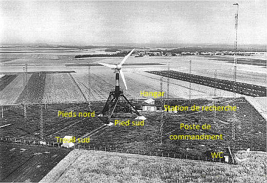
"Lapie" postcard with commentary.
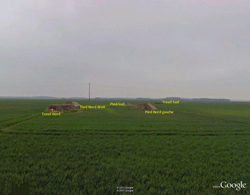
The remains of the wind turbine (Google Street view - 2012).
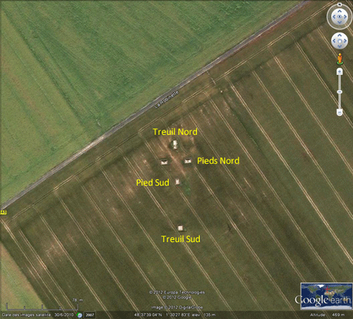
Same as seen from the sky (Google Earth - 2012).
(Click on the pictures to see their actual size).


