Design features |
The BEST-Romani wind turbine in Nogent-le-Roi had the following technical characteristics (see also the summary in figures):
 |
(Click on the pictures to see their actual size).
Wind wheel:
- Three-bladed fixed-pitch propeller made of aluminium-zinc light-alloy sheet (AZ4G). Profile and structure of the "aeroplane wing" type. Length of a blade: 15 metres, i.e. an overall diameter of 30.19 metres. Rotation axis at 32 metres from the ground.
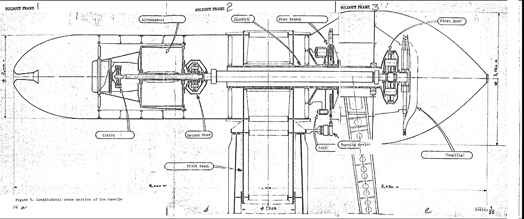
- 6-pole synchronous alternator with a voltage of 3,000 volts transformed into 15,000 volts for connection to the EDF network. The nominal apparent power of 800 KVA or 650 kW. The propeller was connected to the alternator by a coaxial mechanical linkage involving two sets of epicycloidal spur gears.
- Rotation speed: 47 rpm. Alternator rotation speed: 1,000 rpm (invariable as regulated by the 50 Hz frequency of the EDF network).
- A clutch was used to disengage the propeller from the alternator when coupled to the grid.
- The system was equipped with a 1.8-metre diameter disc brake dissipating energy of 2 million kilograms. It was important to be able to brake the wind turbine quickly in very strong winds, otherwise, the wind would supply as much energy as the brake removed, leading to the destruction of the linings and the machine running away in "fan mode".
- Redundant emergency brakes were installed to prevent any runaway:
- by connecting the alternator to an electric resistance line made of nickel silver cooled by the ambient air. This brake, theoretically "emergency", was systematically used to relieve the disc brake linings.
- by a system of spoilers embedded in the leading edge of the blades (aerodynamic braking). Each spoiler was held in its housing by a return spring and a mass individually adjusted according to the position of the spoiler on the leading edge of the blade. At a certain linear velocity, the centrifugal force caused all the spoilers to be ejected at the same time, thus changing the aerodynamic profile of the blade. The circumstances of the tests were such that this unique system was never used, as the machine never ran away with this propeller.
- When stationary, a system of locks prevented any accidental starting of the propeller.
- The unit was housed in a nacelle with a platform at the top accessible to personnel, on which several onboard oil-hydraulic systems (lubrication, brake control, clutch and locks) were installed.
- The weight of the equipped nacelle and propeller assembly was 30 tonnes.
The Pivot:
- Consisting of two trunks of cones of unequal length assembled by their base in opposition.
- The smaller cone was nested inside the tripod pylon and rested on a ball bearing.
- The larger cone emerged from the tower in its entirety.
- The nacelle (above) rested on the upper end of the pivot. It was accessed by a vertical ladder on the back of the pivot between the two metal aerodynamic profiling strips.
- At the point where the two cones meet, a circular metal strip of about 20 cm was welded on. It allowed the rotation of the assembly on a train of rollers embedded vertically in the upper part of the tripod.
- Thanks to these devices, the wind generator worked in "wind vane" mode and was almost automatically oriented in the direction of the wind (propeller towards the back). It was possible to control the orientation of the pivot by a servo mechanism controlled from the experimental room. It was also possible to control the orientation of the windsock at the top of the 60-metre tower.
- Weight of the pivot: 20 tonnes.
The tripod pylon:
- The metal structure of the lattice type.
- Two north-facing legs each rested on a 70 m3 (approx. 150 tonnes) concrete mass via a steel plate.
- The third leg (to the south) rested on a 60 m3 concrete mass (about 100 tonnes). This leg was fixed by a lockable connecting rod.
- The weight of the tripod was 100 tons.
On the ground:
- The alternator voltage was raised from 3,000 to 15,000 volts for connection to the EDF network.
- The line outside the experimental station was connected to the Maintenon SNCF substation by two sections:
- The first, which was temporary and has since disappeared, ran along with the D 148 as far as the path which, bypassing the park of the castle, ensures the connection with the D 104 (Path of Chandres).
- The second went directly to Maintenon through fields and woods.
- At the junction of the two sections, a manually operated overhead inverter made it possible to connect to a third 15,000-volt line serving Nogent-le-Roi directly. This possibility was only used once, as EDF officials feared that the variable output of the wind turbine would disrupt the power supply to the town and its inhabitants.
The tilting :
- The entire machine (150 tons) was tiltable i.e. it was possible to make it describe a circular trajectory of a quarter circle in space to bring it to the horizontal.
- To do this two winches used in coal mines had been installed on two concrete blocks of 50 cubic metres, 8 cubic metres of which were buried, giving them a mass of about twenty tonnes:
- The first winch (called "North") was connected to the upper platform of the tripod by a reeving consisting of a multi-strand steel cable with a diameter of 25 to 30 mm with 6 or 8 strands.
- The second winch (called "South") was connected to the connecting rod of the South leg by an identical but longer reeving system.
- This equipment made it possible, after having oriented the propeller to the North, brought the blades in the adequate angular position and locked the unit, to tilt the whole wind turbine so that at the end of the stroke the propeller was in a horizontal plane.
- The axis of each blade was then in line with the axis of the measuring station terrace or with one of the two branches of a "Y" made of scaffolding tube of the "Entrepose" type. The nose of the propeller was then in a hole located at the connection of the branches of the "Y" and the measuring station. This made it possible to remove the propeller spinner, fairings, gears or alternator without difficulty, whereas this would have been almost impossible on a non-tiltable machine.
The measurement and control station :
- The ground research station included an experiment, control and measurement room.
- At a time when computers were in their infancy, all the measurements were managed by sophisticated electrotechnical devices.
- The start-up was carried out by a series of linked operations requiring the presence of numerous contactors, relays and a multitude of primary contacts (a total of 450 contacts in all).
- The installation had to be in working order at all times so that the experiments could take place at all available wind speeds at any time, i.e. very randomly. To ensure that everything was in working order in the event of wind or to allow for rapid troubleshooting, Pierre Jean Cavey had labelled the hundred or so auxiliary contacts and plotted them on a diagram to allow rapid diagnosis of faults.
- The ground station also contained numerous measuring devices: barometer recorders, a psychrometer, an Ailleret-type energy gauge, others recording the speed and direction of the wind from measurements taken on the 9 pylons, the torque, the forces on the pivot measured by resistance wire extensometers (strain gauges), galvanometers, etc.
- It housed a converter unit connected to the EDF network. The latter turned a direct current generator intended to produce the direct current necessary for the excitation of the inductor of the generator placed in the nacelle. The configuration of the nacelle did not allow the exciter to be installed in the nacelle, which already housed the clutch and a gear train. The unit also ran a second DC generator that powered a battery of backup batteries designed to store enough DC to power the generator in the event of exciter failure.
Launching :
When the wind was favourable (above 2.5 Beaufort and below 8 Beaufort), the tests could be carried out. The wind turbine was started up in a specific sequence:
- Wind up. Operating in "wind vane" mode, it was oriented, as mentioned above, almost into the wind (propeller backwards). "Almost", because for reasons that remain unexplained, the aircraft was oriented with a systematic deviation of about 13 degrees from the real wind direction. The windsock on the 60-metre tower allowed for automatic adjustment. If necessary, the station manager could also make a manual adjustment.
- The generator was then switched on, coupled to the grid, with the propeller disengaged and stopped. This configuration allowed the generator to synchronise with the EDF grid frequency (50 Hz) and to stabilise its speed at 1,000 rpm.
- Only then did the disc brake release the propeller. The coupling between the propeller and the generator was then done by engaging the propeller on the generator.
(Sources: handwritten notes by Pierre Jean Cavey dated October 31, 1994. The above text has been revised by my father in May 5, 2004).
Last update: May-17-2021 19:42:22 CEST

Back to the top of the page
Back to the top of the page