The measuring station |
In the late 1950s and early 1960s, when computers were almost non-existent and unaffordable, the research station was equipped with electrical measurement and control equipment that may seem outdated today but was state of the art at the time.
The station had the honour of being visited by Francis Perrin then High Commissioner for Atomic Energy, and by the Engineer General of Maritime Engineering, Albert Caquot in charge of the Rance dam project (1961-1966).
Note: the three-phase 220~380 volts / 50Hz current that is distributed today in France was not yet distributed in those years. The station was supplied with three-phase 127~220 volts / 50 Hz by the step-down transformer.
 |
|
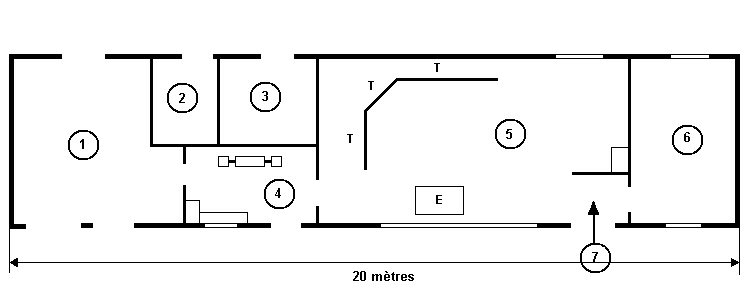
1- Transformer station : |
4- Office of the station manager and converter unit. 5- Experimentation and measurement room. 6- Small workshop. 7- Entrance. E- Measurement recording post. |
| (from a freehand drawing made from memory by P.-J. Cavey on 6 May 2004) | |
 |
|
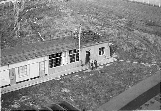
| The measurement and control station seen from the tripod. | |
 |
|
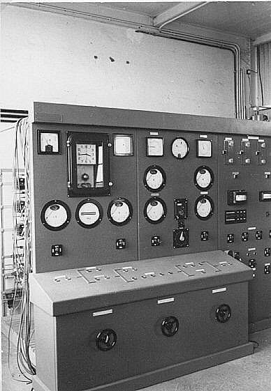
| Control panel. | |
 |
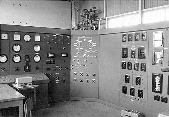 |
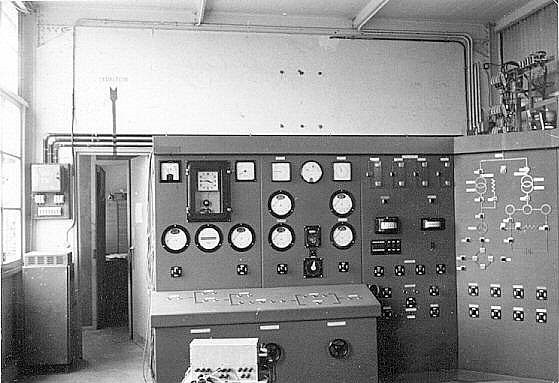
| The control panel and the control board for electrical engineering. | |
 |
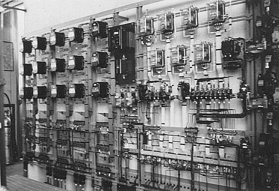 |
| On the right, the backstage area (seen from behind the control panel). | |
 |
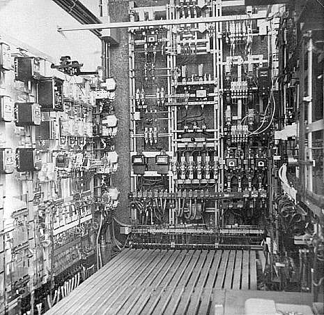 |
| There were about 450 primary contacts, relays and contactors of all kinds. | |
 |
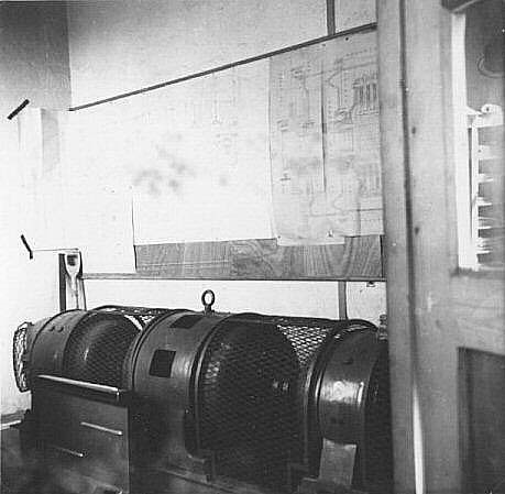 |
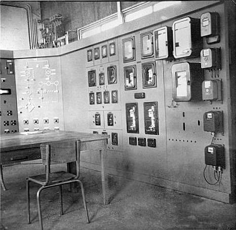
The director's austere office. On the right the converter group. |
This 127~220 three-phase converter set, connected to the EDF 50 Hz grid, allowed two DC generators to be "turned". One (inductor) fed the inductor of the wind turbine generator; The other fed a battery of backup batteries placed on the other side of the partition. |
Back to the top of the page